


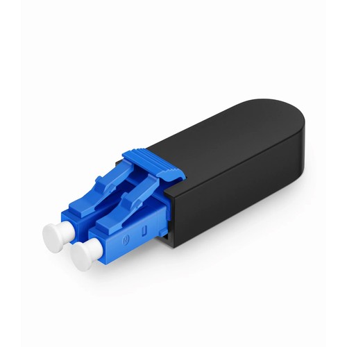
For Nigerian deployments, this product should be evaluated as part of the complete network path, including its connectors, mapping and acceptance values. This fiber loopback module provides a self-contained optical path that returns the transmit signal directly into the receive channel of the port under test: 2F, OS2, in a LC configuration. A fixed 3dB attenuator sits inside the loop, which means the transceiver sees a realistic channel loss budget rather than a zero-loss short circuit - the difference between a port that merely lights up and a port that is proven against real loss conditions.
Product Highlights
- Easy Insertion and Extraction with Push-Pull Design
- Low Insertion Loss ≤0.3dB, High Return Loss ≥50dB
- Ideal for Port Provisioning, Testing, and Troubleshooting
- Compact LC Single Mode Design for Fiber Testing
- Integrated 3dB Attenuation for Direct Tx/Rx Loopback
Specifications
| Fiber Type | OS2 9/125μm |
|---|---|
| Fiber Connector | LC/UPC |
| Attenuation | 3dB |
| Attenuation Tolerance | ±0.5dB |
| Insertion Loss | ≤0.3dB |
| Return Loss | ≥50dB |
| Housing Material | PC |
| Mating Cycles | 500 times |
| Dimensions (HxWxD) | 14.4x12x51mm |
| Operating Temperature | -40 to 75°C (-40 to 167°F) |
| Storage Temperature | -40 to 75°C (-40 to 167°F) |
What loopback testing actually proves
A loopback module closes the optical circuit inside one device: the transmitter launches light, the test module returns it, and the receiver must lock onto its own signal. When the link comes up clean under those conditions, the port has proven its transmitter power, its receiver sensitivity and its internal signal integrity in one step. It is the fastest way to individual a bad port from a bad cable plant, as the cable assembly plant is entirely removed from the test.
Why an attenuated loopback tells more
A zero-loss loopback proves the optics function; it does not itself prove they function at the link loss calculation the real link will impose. The fixed 3dB attenuator inside the test module simulates the interface connector pairs and fiber span of a real channel, which means the receiver must work at a realistic power level. Ports with marginal receiver sensitivity - the ones that fail three months after deployment - are caught at the bench instead of in the field.
Using 3dB in a test plan
Three decibels approximates the loss of a short haul with a couple of mated connector pairs: a realistic operating point for single-mode links. When the test plan calls for margins, engineers step through power levels with a variable attenuator; when it calls for a fast, uniform pass/fail at a realistic budget, a fixed 3dB loopback is this maintenance tool that stays in the kit.
Looping duplex transceiver ports
Duplex LC and SC ports - SFP, SFP+ and similar form factors - are tested one port at a time. The loopback seats into the cage like a patch cord and stays latched for the duration of the test, leaving the two hands free for the console. Because the test module is a single solid body, there is no cord to kink and no polarity to arrange: transmit returns to receive by construction.
Keeping single-mode test hardware clean
Single-mode testing is unforgiving about contamination: a dust particle on the ferrule adds loss that masquerades as a failing receiver. Keep the dust cap on the test module whenever it cannot be considered mated, inspect the ferrule before insertion, and clean with a suitable ferrule cleaner rather than improvised materials. A loopback that lives in a pocket without its cap will eventually fail good ports.
Handling, wear and service life
A loopback module is a precision test tool, and it stays one only while its latch, housing and ferrule survive daily duty. The insert-pull rating is generous, but it cannot be considered infinite: track the mating count in the test log, and retire a module that has served a production line for years before its wear becomes the hidden cause of failing ports. A worn latch that seats loosely adds loss that masquerades as a bad receiver - the cheapest instrument in the kit might waste the most expensive hours.
A bench test workflow that scales
The productive way to use loopbacks is a fixed routine: inspect the test module ferrule, mate it with the port, bring the interface up, record the per-lane status and the receive power, then unmate and cap the test module immediately. With the routine fixed, a technician qualifies a full chassis of ports in the time an improvised setup spends on one line card. The consistency also makes the records comparable - the same module, the same procedure, the same pass criteria across each site and each batch of hardware.
Sparing and kit planning
Loopbacks belong in each commissioning kit the way a known-good patch cord does. Plan one module per interface type per crew, plus a spare that stays sealed in its bag; the cost of an extra module is trivial against a truck roll to re-test a suspect port. Label every module with its interface, fiber count and attenuation so the right one comes out of the bag on the first try, and log its insertion count so a worn test tool never becomes the hidden cause of failing ports.
Selecting the right loopback for the task
Four decisions define the test module: the interface connector interface must correspond to the port under test, the fiber count must cover the lanes the optics use, the allocation type must pair the lanes the way the transceiver expects, and the attenuation must reflect the link loss calculation the test plan calls for. Getting all four right at order time is what turns a loopback from a drawer of adapters into a dependable instrument. When the requirement sits outside the standard configurations, the factory might establish a project-specific build - connector combinations, allocation variants and other attenuation data are all manufacturable options.
Inspection and Test Procedures
Each loopback module is optically tested before packing: insertion loss of the whole loop is verified against the specification, and the ferrule end faces are inspected for scratches and contamination. The test module ships with its dust cap fitted and the test result available on request.
Ordering Information and Support
Refer to the test module by connector interface, fiber count, polish and attenuation at the request stage a quotation. For other attenuation data, allocation types or connector combinations, send the test requirement with the enquiry and the factory will establish the manufacturable specification. For Nigerian orders, our team can check the requirement before coordinating manufacture and international delivery.


